Precise Time Sync & iSCSI

It’s a good feeling to kill two birds with one stone (figuratively) when delivering an IT project. I had the opportunity to do just that recently when two separate business units offered up two very different problems that I could solve at the same time. The first requirement was time synchronisation using PTPv2, or IEEE1588-2008 Precision Time Protocol, to synchronise devices in multiple buildings within our campus (approximately 2000 fibre route meters from end to end). The second requirement was an iSCSI network between the same locations for SAN replication between multiple pairs of disparate buildings. 

Our current LAN network at the time just didn’t support PTP. I’m sure we could have made it work somehow by using multicast routing, but the sub 50 microsecond precision required for the application wouldn’t have been achievable. It was obvious that we needed some new switches. Initially I was looking at Cisco’s industrial switches since we already had some deployed in the network.

As for the iSCSI requirement, we needed multiple 10Gig uplinks to every SAN. Again, our current LAN network at the time didn’t have the capacity to accommodate that many 10Gig ports, so it was also apparent that new switches were required to run a separate SAN network. 

After a lot of Googling for high density 10Gig switches, I came across some Nexus switches that also happened to support PTP. They had 32 x 10Gig SFP+ ports each. My thought process ended up something like: Ideal. WOW Expensive! Let’s try Ebay. Ideal.

We ended up buying 8 x Nexus 5548up switches from Ebay, with the L3 daughter board and L3 license (i’ll explain why later). The switches ended up costing around £1,500 each, instead of £25k+ per switch new.

To provide an accurate time source we also purchased a Meinberg GPS / GNSS PTP grandmaster clock. This also turned out to provide NTP as well, so our domain has a pretty precise time source now, but that’s a different story.
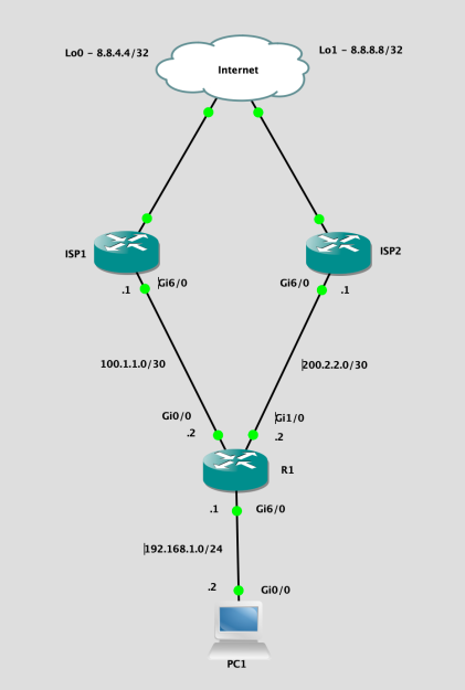
Physical Topology

Now the topology of the switches is as follows. topology_1.jpg We decided to go with this topology to allow us to add an additional grandmaster clock at a later date in the second “hub” location. Since both hubs are on different substations etc, this would provide some resilience if and when required. Wed also have an abundance of disparate fibre between all of the facilities and the two hubs, as these are are main datacenter locations. 

PTP

The PTP logical topology looks a little something like this.topology_2.jpg
Each switch is configured to be a boundary clock in the PTP domain. The PTP priorities of the switches mean that if the grandmaster goes offline for whatever reason, the switches will all synchronise to the lowest priority switch. This was done to ensure the equipment in all facilities were in sync with each other, even if they weren’t in sync with actual time. If a facility becomes isolated from he rest of the network, then at least its clocks will all remain in sync with each other since the switch in that facility has a lower priority than the default PTP priority.

The PTP ports are on a vlan local to the switch. Since the switches are boundary clock, there doesn’t need to be layer 2 adjacency between the grandmaster clock and the clocks (devices) for PTP to work. The port configuration is simple and is as follows.

You don’t even need to configure ip addresses on the local vlan. The devices will use link local addresses and multicast to communicate with the switch. No pesky VRF’s required!

iSCSI

The iSCSI topology ended up being Layer 3 between the buildings. We didn’t want to stretch Vlan’s between the buildings to help contain outages. The operational facilities are test & validation facilities with a lot of moving mass or high voltage, so the likelihood of a switch being taken out is pretty high. To propagate routes we used OSPF, with the hubs being area 0 and each facility having it’s own area. The logical iSCSI topology looks like this.topology_1.jpg I’ve only included the information for two of the four facilities to make it more legible.

I’m aware that some people don’t like using layer 3 in iSCSI networks. In our situation, the replication is asynchronous. In each building the iSCSI initiator and target are both on the same subnet / vlan. Only the replication traverses layer 3 boundaries. We haven’t seen any performance or reliability issues with this topology yet so all is good. 

Final Observations / Notes

One caveat of the Nexus 5548up switches is that the ports cannot run at 100Mbit/s. This is an issue for some PTP devices as they only have 100Mbit/s ports. To get around this we used cheap media converters from FS.com. These media converters will happily have a 1Gbit/s SFP in the SFP port, and a 100Mbit/s connection in the RJ45 port. 

Another caveat of the Nexus 5548up switches is that if you want to run a port at 1Gbit/s with an RJ45 SFP, you must force the port to 1000Mbit before it will come up. Just add speed 1000 to the port configuration.

Buying Cisco SFP’s isn’t really worth it when using used switches. Even on Ebay a used one is around £35-60 and you don’t know what sort of environment it’s been in. FS.com sell compatible optics for £19 with a 5 year warranty.

We also purchased spare switches for a quick response to a failure. We could have doubled down and deployed two per facility, but didn’t think it was necessary. The clock devices only have a single port at the end of the day, and SAN replication can catch up.

That’s it. I just thought I’d share one of those little last minute projects that needs to be delivered on a  tight budget.

Cisco Router Dual WAN Uplinks with NAT

Dual WAN uplinks for resilience are a common request when configuring small business routers. I’ll work with the topology below and go through the configuration.

Screenshot 2020-02-13 at 20.56.40.png

The only devices I’ll be going over are R1 and PC1. In the real world, the rest would be out of your control anyway. I’ll include the GNS3 project file at the end of this post if you would like to play with it.

Configuration

The first thing we need to do is configure the interfaces of the two ISP connections.

interface GigabitEthernet0/0
  description ISP1
  ip address 100.1.1.2 255.255.255.252
  ip nat outside
!
interface GigabitEthernet1/0
  description ISP2
  ip address 200.2.2.2 255.255.255.252
  ip nat outside
!

And the LAN interface

interface GigabitEthernet6/0
  description LAN
  ip address 192.168.1.1 255.255.255.0
  ip nat inside
!

Next we’ll configure our routes via both ISP’s. To make the failover work we need to track some objects on the primary connection. This will make failover occur if the internet connection goes down. I would advise you track reachability of a couple of hosts to avoid failing over if somebody else is having an issue. I would also advise against tracking the next hop, as an issue within the ISP network wouldn’t cause failover to occur but may prevent you from reaching the internet. We do this using ip sla to two different known hosts (I used Google’s public DNS servers for this demo).

ip sla 100
icmp-echo 8.8.8.8 source-interface GigabitEthernet0/0
threshold 1000
timeout 1000
frequency 10
ip sla schedule 100 life forever start-time now
ip sla 101
icmp-echo 8.8.4.4 source-interface GigabitEthernet0/0
threshold 1000
timeout 1000
frequency 10
ip sla schedule 101 life forever start-time now

Next we create two track objects to monitor the ip sla’s for reachability.

track 100 ip sla 100 reachability
!
track 101 ip sla 101 reachability

Then a track object to track the first two objects. By using the boolean or option, the track will go down if all of the tracked objects go down but will not if only one goes down.

track 105 list boolean or
object 100
object 101

Now we will add our default routes via both ISP’s. We will use the track 105 object to determine if ISP1 is up and add it to the routing table. Otherwise we will add ISP2 with a metric of 10.

ip route 0.0.0.0 0.0.0.0 100.1.1.1 track 105
ip route 0.0.0.0 0.0.0.0 200.2.2.1 10

That should be the routing done, now we will need to configure NAT to allow the LAN clients to access the internet. We’ll create an access list to define the LAN traffic that should be translated.

ip access-list standard NAT-INSIDE
permit 192.168.1.0 0.0.0.255
!

And we’ll use some route-maps to match the LAN traffic on the outside interfaces for translation.

route-map RM-NAT-ISP2 permit 20
match ip address NAT-INSIDE
match interface GigabitEthernet1/0
!
route-map RM-NAT-ISP1 permit 10
match ip address NAT-INSIDE
match interface GigabitEthernet0/0
!

And finally, the NAT configuration commands.

ip nat inside source route-map RM-NAT-ISP1 interface GigabitEthernet0/0 overload
ip nat inside source route-map RM-NAT-ISP2 interface GigabitEthernet1/0 overload

Verification

Now we can do some testing. If we ping from PC1 to 8.8.8.8, the ping should succeed. You can also perform a traceroute from PC1 to 8.8.8.8 to verify the route the traffic flows.

PC1#ping 8.8.8.8
Type escape sequence to abort.
Sending 5, 100-byte ICMP Echos to 8.8.8.8, timeout is 2 seconds:
!!!!!
Success rate is 100 percent (5/5), round-trip min/avg/max = 48/85/196 ms

PC1#traceroute 8.8.8.8
Type escape sequence to abort.
Tracing the route to 8.8.8.8
VRF info: (vrf in name/id, vrf out name/id)
1 192.168.1.1 16 msec 48 msec 28 msec
2 100.1.1.1 104 msec 72 msec 44 msec
3 1.2.1.1 56 msec 60 msec 68 msec

You can use show ip nat translations on R1 to verify the NAT translations over ISP1.

R1#show ip nat translations
Pro Inside globalInside local Outside localOutside global
icmp 100.1.1.2:1025192.168.1.11:168.8.8.8:16 8.8.8.8:1025
udp 100.1.1.2:4501 192.168.1.11:49157 8.8.8.8:334378.8.8.8:33437
udp 100.1.1.2:4502 192.168.1.11:49158 8.8.8.8:334388.8.8.8:33438
udp 100.1.1.2:4503 192.168.1.11:49159 8.8.8.8:334398.8.8.8:33439
udp 100.1.1.2:4504 192.168.1.11:49160 8.8.8.8:334408.8.8.8:33440
udp 100.1.1.2:4505 192.168.1.11:49161 8.8.8.8:334418.8.8.8:33441
udp 100.1.1.2:4506 192.168.1.11:49162 8.8.8.8:334428.8.8.8:33442

And also, show ip route on R1 should show the next hop as ISP1.

S*    0.0.0.0/0 [1/0] via 100.1.1.1

Now, if we suspend a link connected to the ISP1 route, it doesn’t matter which one, our topology should failover.

Screenshot 2020-02-13 at 21.44.38.png

First thing you should notice is the track objects going down on R1.

*Feb 13 21:44:28.847: %TRACKING-5-STATE: 100 ip sla 100 reachability Up->Down
*Feb 13 21:44:28.851: %TRACKING-5-STATE: 101 ip sla 101 reachability Up->Down
*Feb 13 21:44:29.835: %TRACKING-5-STATE: 105 list boolean or Up->Down

And the default route on R1 should have changed to ISP2.

S*0.0.0.0/0 [10/0] via 200.2.2.1

And if we repeat the same ping and traceroute from PC1 to 8.8.8.8, they should still work fine, but the route should show ISP2 as the second hop instead of ISP1.

PC1#ping 8.8.8.8
Type escape sequence to abort.
Sending 5, 100-byte ICMP Echos to 8.8.8.8, timeout is 2 seconds:
!!!!!
Success rate is 100 percent (5/5), round-trip min/avg/max = 28/56/84 ms

PC1#traceroute 8.8.8.8
Type escape sequence to abort.
Tracing the route to 8.8.8.8
VRF info: (vrf in name/id, vrf out name/id)
1 192.168.1.1 12 msec 88 msec 24 msec
2 200.2.2.1 52 msec 32 msec 36 msec
3 1.2.2.1 64 msec 64 msec 36 msec

show ip nat translations on R1 should also show the NAT translations to ISP2 now.

R1#show ip nat translations
Pro Inside globalInside local Outside localOutside global
icmp 200.2.2.2:1024192.168.1.11:2 8.8.8.8:28.8.8.8:1024
udp 200.2.2.2:4501 192.168.1.11:49167 8.8.8.8:334378.8.8.8:33437
udp 200.2.2.2:4502 192.168.1.11:49168 8.8.8.8:334388.8.8.8:33438
udp 200.2.2.2:4503 192.168.1.11:49169 8.8.8.8:334398.8.8.8:33439
udp 200.2.2.2:4504 192.168.1.11:49170 8.8.8.8:334408.8.8.8:33440
udp 200.2.2.2:4505 192.168.1.11:49171 8.8.8.8:334418.8.8.8:33441
udp 200.2.2.2:4506 192.168.1.11:49172 8.8.8.8:334428.8.8.8:33442

Now if we resume the link to the ISP1 route, the track objects will come back up and everything should fail back.

*Feb 13 21:50:43.871: %TRACKING-5-STATE: 100 ip sla 100 reachability Down->Up
*Feb 13 21:50:43.871: %TRACKING-5-STATE: 101 ip sla 101 reachability Down->Up
*Feb 13 21:50:44.839: %TRACKING-5-STATE: 105 list boolean or Down->Up

Notes

There are a couple of things to note with this configuration:

  • There is zone-based firewall configuration in this demo. I highly recommend one if you aren’t using a dedicated firewall.
  • Inbound connections using port forwarding and the primary connection IP address will not failover if ISP1 fails.
  • The IOS image used in this GNS project is c7200-advipservicesk9-mz.152-4.S5.bin. You’ll have to provide that yourself.

Downloads

GNS3 Project – Dual WAN

Playing with interface templates in Cisco IOS XE

I recently learned of the existence of interface templates. Previously I had been using int range a lot to make mass updates to our access ports, but this wasn’t really scaling well and took ages to do on some of our 7 switch stacks.

For anybody who hasn’t used interface templates before, they are a mechanism to configure once and apply to many interfaces. Not only is this convenient, it reduces the size of your configuration quite a bit.

We built a number of templates for use in our network, one for each vlan we assign ports to. Since we standardised the access vlans across all switches (e.g. vlan 100 is always for users, vlan 200 is always for voice, vlan 600 is always for guest access etc), this makes all the templates across all switches identical.

What goes into a template? pretty much any configuration you can apply to an interface, you can put in a template. Heres an example of a template for a user port.

template USER
 storm-control broadcast level pps 1k
 storm-control action shutdown
 spanning-tree portfast
 spanning-tree bpduguard enable
 spanning-tree guard root
 switchport access vlan 100
 switchport mode access
 switchport voice vlan 200
 switchport port-security maximum 2
 switchport port-security violation protect
 switchport port-security aging time 3
 switchport port-security
 service-policy input MARKING
 service-policy output 2P6Q3T-WRED
 description USER
!

And then to apply it to an interface:

interface Gi1/0/25
 source template USER
!

Thats literally all of the configuration you need on an interface. The problem now is, if you do a show run on an interface, all you get is “source template USER”. There is a different show command to solve that problem.

SW1#show derived-config interface gi1/0/25
Building configuration...

Derived configuration : 501 bytes
!
interface GigabitEthernet1/0/25
 description USER
 switchport access vlan 100
 switchport mode access
 switchport voice vlan 200
 switchport port-security maximum 2
 switchport port-security violation protect
 switchport port-security aging time 3
 switchport port-security
 storm-control broadcast level pps 1k
 storm-control action shutdown
 spanning-tree portfast
 spanning-tree bpduguard enable
 spanning-tree guard root
 service-policy input MARKING
 service-policy output 2P6Q3T-WRED
end

You can also mix and match on an interface, and have configuration directly on the interface. The the interface configuration will override the template configuration. It still looks a bit weird in show run though.

template USER
 storm-control broadcast level pps 1k
 storm-control action shutdown
 spanning-tree portfast
 spanning-tree bpduguard enable
 spanning-tree guard root
 switchport access vlan 100
 switchport mode access
 switchport voice vlan 200
 switchport port-security maximum 2
 switchport port-security violation protect
 switchport port-security aging time 3
 switchport port-security
 service-policy input MARKING
 service-policy output 2P6Q3T-WRED
 description USER
!
interface Gi1/0/25
 description Marketing Laptop
 source template USER
!

SW1#show run int gi1/0/25
Building configuration...

Current configuration : 92 bytes
!
interface GigabitEthernet1/0/25
 description Marketing Laptop
 source template USER
end

SW1#show derived-config interface gi1/0/25
Building configuration...

Derived configuration : 506 bytes
!
interface GigabitEthernet1/0/25
 description Marketing Laptop
 switchport access vlan 100
 switchport mode access
 switchport voice vlan 200
 switchport port-security maximum 2
 switchport port-security violation protect
 switchport port-security aging time 3
 switchport port-security
 storm-control broadcast level pps 1k
 storm-control action shutdown
 spanning-tree portfast
 spanning-tree bpduguard enable
 spanning-tree guard root
 service-policy input MARKING
 service-policy output 2P6Q3T-WRED
end

I found interface templates really useful during a recent network upgrade. It wasn’t too long ago I became CCNA certified and these weren’t even mentioned on the courses, which is a shame.

These templates are configured on 9200L switches, if you are interested.

SharePoint 2013 or 2016 and ADFS

Ever wondered how to configure SharePoint to use ADFS for user authentication? Googled it and found it confusing? Me too! Don’t despare though… the Powershell is pretty straightforward and it only gets easier the more often you do it…

Export ADFS Signing Certificate

First of all log in to the ADFS server and export the signing certificate.  The following powershell should be ran as administrator and will export the certificate to c:\ADFSSigning.cer.


$certBytes=(Get-AdfsCertificate -CertificateType Token-Signing)[0].Certificate.Export([System.Security.Cryptography.X509Certificates.X509ContentType]::Cert)

[System.IO.File]::WriteAllBytes("c:\ADFSSigning.cer", $certBytes)

If your ADFS signing certificate was issued by a certificate authority and not self-signed by ADFS, you must ensure the entire certificate chain is trusted by SharePoint as well. I won’t cover this process here, but you can refer to another post on the topic here.

Add ADFS Relying Party Trust

While you are on your ADFS server, you may as well create the relying party trust in, you guessed it, powershell. But first you need to make a txt file with the following contents. For ease, lets say c:\rules.txt. These are the transformation rules for the relying party. I find this is all that is really required to start with as User Profile Sync will grab the rest.


@RuleTemplate = "PassThroughClaims"
@RuleName = "SharePoint Attributes"
c:[Type == "http://schemas.microsoft.com/ws/2008/06/identity/claims/windowsaccountname", Issuer == "AD AUTHORITY"]
=> issue(store = "Active Directory", types = ("http://schemas.xmlsoap.org/ws/2005/05/identity/claims/emailaddress", "http://schemas.xmlsoap.org/ws/2005/05/identity/claims/upn", "http://schemas.xmlsoap.org/ws/2005/05/identity/claims/surname", "http://schemas.xmlsoap.org/ws/2005/05/identity/claims/givenname"), query = ";mail,mail,sn,givenName;{0}", param = c.Value);

Then edit the variables in the powershell below and execute it. Here a quick explanation of the variables.
$rules – The path to the rules.txt files you have just created.
$name – The name of the relying party trust.
$urn – If you don’t know what this is, just leave it.
$webapp – The URL for the first web application you are going to use. I’ll show you how to add another application later. Don’t put a trailing slash on the URL.

$rules = "c:\rules.txt"
$name = "SharePoint Site 1"
$urn = "urn:sharepoint:site1"
$webapp = "https://site1.domain.local"
$endpoint = $webapp + "/_trust/"
[string[]] $urnCollection = $urn, $webapp

Add-AdfsRelyingPartyTrust -Name $name -ProtocolProfile WSFederation -WSFedEndpoint $endpoint -Identifier $urnCollection -IssuanceTransformRulesFile $rules

You can now go and check in the ADFS console and yor new trust should be listed under Relying Party Trusts.

Add Token Signing Certificate to SharePoint

Log in to the SharePoint server that hosts central admin and copy the ADFSSigning.cer file to the C drive then open the SharePoint Management Shell as administrator. The following powershell will import the certificate so that SharePoint trusts it.


$path = “C:\ADFSSigning.cer”
$root = New-Object System.Security.Cryptography.X509Certificates.X509Certificate2($path)
New-SPTrustedRootAuthority -Name "ADFS Token Signing Cert" -Certificate $cert
//Keep this window open for the next step

Again, of your ADFS signing certificate was issued by a Certificate Authority instead of being self-signed by ADFS, you must make sure SharePoint trusts all other certificates in the chain.

Create The Authentication Provider In SharePoint

To add ADFS as a Authentication Provider to SharePoint, use the following powershell in the same windows that you imported the certificate in:

//Map the email address, UPN, Group Memberships and SID from ADFS
$emailClaimMap = New-SPClaimTypeMapping -IncomingClaimType "http://schemas.xmlsoap.org/ws/2005/05/identity/claims/emailaddress" -IncomingClaimTypeDisplayName "EmailAddress" -SameAsIncoming
$upnClaimMap = New-SPClaimTypeMapping -IncomingClaimType "http://schemas.xmlsoap.org/ws/2005/05/identity/claims/upn" -IncomingClaimTypeDisplayName "UPN" -SameAsIncoming
$roleClaimMap = New-SPClaimTypeMapping -IncomingClaimType "http://schemas.microsoft.com/ws/2008/06/identity/claims/role" -IncomingClaimTypeDisplayName "Role" -SameAsIncoming

//Update the following to match the details entered earlier if you changed them
$realm = "urn:sharepoint:site1"
$signInURL = "https://adfs.domain.local/adfs/ls"
$ap = New-SPTrustedIdentityTokenIssuer -Name ADFS -Description ADFS -realm $realm -ImportTrustCertificate $cert -ClaimsMappings $emailClaimMap,$upnClaimMap,$roleClaimMap,$sidClaimMap -SignInUrl $signInURL -IdentifierClaim $emailClaimmap.InputClaimType

Providing you don’t get any error, SharePoint should now be able to use ADFS as a authentication provider.

Change SharePoint Application to Claims Based

Now you need to make one of your SharePoint web applications use ADFS for authentication. There are a number of caveats with this though:

  • You will lose access to the web application as your permission is set on the account SharePoint knows of from windows authentication. I’ll show you how to fix this soon.
  • Your user profile will not be associated with your account any more. This is again because the User Profile Service has synced your profile with Active Directory using your windows account.
  • Search will be unable to crawl the SharePoint site as it doesn’t support claims based authentication.

I’ll show you how to fix these things in a future post, otherwise this post will end up being a monster.

For now, I’d recommend performing these steps on a newly created SharePoint Web Application of your choosing. The commands assume a site called https://site1.domain.local.

Open up the SharePoint management shell as administrator and run the following commands:

$webApp = Get-SPWebApplication -Identity "https://site1.domain.local"
$sts = Get-SPTrustedIdentityTokenIssuer "ADFS"
Set-SPWebApplication -Identity $webApp -AuthenticationProvider $sts -Zone "Default"

If you now try to access the site you should be redirected to your ADFS sign-in page. Once you login, you will probably get the “This site hasn’t been shared with you” message. Keep reading for a fix.

Changing More SharePoint Applications to Claims Based

The above powershell will certainly allow you to change another web application across to claims based authentication, but with one little issue. Upon doing so, every time you try to access the second web application you will end up back at the first one after you login. This is because the realm of the second web app is different, and ADFS will just send you straight to the first site configured. Luckily thought there is no need to mess on with certificates for the second site.

On the SharePoint server, open the SharePoint Management Shell as admin and use the following commands to add another realm to the authentication provider:


$urn = "urn:sharepoint:site2"

$ap = Get-SPTrustedIdentityTokenIssuer
$uri = new-object System.Uri("https://site2.domain.local")
$ap.ProviderRealms.Add($uri, $urn)
$ap.Update()

Then you need to add another Relying Party Trust in ADFS to handle requests for the second SharePoint site. To do this, follow the steps in the section of this post Add ADFS Relying Party Trust, but remember to update the strings in the powershell commands to represent your second site.

Regain Access to Site With Claims Based Authentication

Now that your site(s) are claims based authentication enabled, you need to re-add yourself as a site collection administrator. The following powershell will set your ADFS formatted account as the secondary site collection owner. You can also do this in central admin but I won’t go into that route in this post.


Set-SPSite –Identity "https://site1.domain.local" –SecondaryOwnerAlias "emailaddress@domain.local"

Updating the Signing Certificate in SharePoint

For whatever reason Microsoft hasn’t given, SharePoint can’t use the Federation Metadata issued by ADFS to update the Signing Certificate when it is renewed at the end of its validity period, leaving it up to the administrator to do this manually.

The process of updating the certificate isn’t particularly complex. It’s basically export the new certificate, then install it and import it on the SharePoint server before updating the Trusted Token Issuer in SharePoint to use the new certificate. The problem is though that if you forget to update the certificate in the brief period between the ADFS server renewing it’s certificate and the old certificate expiring, nobody will be able to login to SharePoint. And trust me, you WILL forget at least once.

Fortunately, Jesus Fernandez has a solution over on MSDN in the form of a powershell script that can be scheduled to run on the SharePoint server. The script reads the afor mentioned Federation Metadata from ADFS and downloads the current token signing certificate. If it is different to the one SharePoint is using, it adds it to SharePoint and updates the Token Issuer in SharePoint to use the new certificate. Nifty huh? I’d strongly recommend this as a solid option.

Workflow Manager Configuration Error

I recently attempted to configure Workflow Manager 1.0 and Service Bus 1.0 for use by SharePoint 2016, using a certificate issued by our domain CA instead of self-generated certificates. I ran into the following error though.

System.Management.Automation.CmdletInvocationException: Could not successfully send message to scope ‘/WF_Management’ despite multiple retires over a timespan of 00:02:07.8300000.. The exception of the last retry is: A recoverable error occurred while interacting with Service Bus. Recreate the communication objects and retry the operation. For more details, see the inner exception..  —> System.TimeoutException: Could not successfully send message to scope ‘/WF_Management’ despite multiple retries over a timespan of 00:02:07.8300000.. The exception of the last retry is: A recoverable error occurred while interacting with Service Bus. Recreate the communication objects and retry the operation. For more details, see the inner exception..  —> System.OperationCanceledException: A recoverable error occurred while interacting with Service Bus. Recreate the communication objects and retry the operation. For more details, see the inner exception. —> Microsoft.ServiceBus.Messaging.MessagingCommunicationException: Identity check failed for outgoing message. The expected DNS identity of the remote endpoint was ‘WFMServer1.contoso.com’ but the remote endpoint provided DNS claim ‘WFMServer3.contoso.com’. If this is a legitimate remote endpoint, you can fix the problem by explicitly specifying DNS identity ‘WFMServer3.contoso.com’ as the Identity property of EndpointAddress when creating channel proxy.  —> System.ServiceModel.Security.MessageSecurityException: Identity check failed for outgoing message. The expected DNS identity of the remote endpoint was ‘WFMServer1.contoso.com’ but the remote endpoint provided DNS claim ‘WFMServer3.contoso.com’. If this is a legitimate remote endpoint, you can fix the problem by explicitly specifying DNS identity ‘WFMServer3.contoso.com’ as the Identity property of EndpointAddress when creating channel proxy.

To cut a long troubleshooting story short, the problem was with the certificate I had requested from the CA. More specifically the DNS extension. I had the following DNS entries in the certificate.

  1. *.contoso.com
  2. WFMServer1.contoso.com
  3. WFMServer2.contoso.com
  4. WFMServer3.contoso.com

For what ever reason, WFM only seems to look at the final DNS entry when trying to add the host to the WFM farm. To confirm this, I tried the installation from all three hosts and it worked fine on WFMServer3.contoso.com, but not the other 2.

I’m still not entirely sure if it was WFM or SB that was causing this issue, but I fixed it by simply revoking the certificate on our CA and re-installing SB and WFM using a certificate with wfm.contoso.com as the Common Name and DNS entries in the following order:

  1. WFMServer1.contoso.com
  2. WFMServer2.contoso.com
  3. WFMServer3.contoso.com
  4. *.contoso.com